A long post about an amateur homemade piece of hardware. A lot of blurry photos.
This is a translation of the original post in Ukrainian.
There are many different ready-made stepper motor drivers and ready-to-use motor shields: take it and use it. But I had a wish to make my own board with my very specific needs.
Well. I did it.
The purpose of the project
The first point: I love the little cheap 5-volt unipolar stepper motors 28BYJ-48. Yeah, I know, unipolar motors are inefficient, and 5-volt ones are very slow, low-power and not worth paying attention to. But unipolar ones are much simpler and do not require a complex driver. Say in general, expensive powerful bipolar motors in heavy square NEMA cases, which are usually found in 3D printers, CNC machines and other serious things, are something industrial, and the small “toy” 28BYJ-48 just fits my idea of the hobby scale.
The second point: I don’t want to use those ubiquitous small driver boards assembled with the ULN2003 family chip; I want to use the chip itself (in my case it’s ULN2003AN) without extra wires and LEDs.
The third point: usually the motor shields are made for large boards with a large number of GPIOs — Arduino Uno, Nano or even Mega. Instead I want to use shift registers from the 74HC595 family, to be specific SN74HC595N which I had.
Combining a 74HC595 and a ULN2003 seems like a trivial idea, right?
Only three GPIO pins need to control the shift register, which means even the ESP8266 (always lacking free GPIOs) will fit. The idea is as follows: two chained 74HC595, two ULN2003, contacts for three 28BYJ-48 stepper motors, contacts for WeMos D1 mini.
The circuit has no discrete components, not even a single resistor, only contacts.
The scheme
I got my hands on Fritzing and began to draw. Decided to fit everything on the simplest, cheapest single-sided getinax (FR-2) perfboard, the one sized 18x24 holes. So it would not be a big deal if I solder something wrong. Classic through-hole technology, the simplest approach.
The scheme was named shift_stepper, then shift_stepper_alt, alt_2, alt_3, alt_4, alt_4a, alt_4b and finally the final version is alt_4c. Damn why I kept all them alongside together in the version control system :)
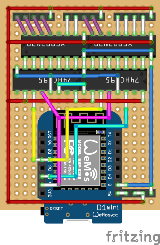
The colored wires in the scheme are actually wires (and almost all of them are on top). White “wires” are drops of solder stretched by a soldering iron between individual metalized holes on the board. I tried not to overuse this technique, but there’s no way to avoid it.
The lower half of the scheme is obviously far from optimal. ESP is stupidly stuck in the center.
Well, at the bottom of the circuit, everything important is arranged more or less obviously: the three shift register control wires ST_CP, DS and SH_CP somehow go there to pins D8, D7 and D5, respectively. (Why did I choose these pins? Because that way I can use the hardware SPI).
A some mess in the lower right corner, where the power inlet is. The idea is that the +5V of the main board is connected to the 5V contact on the D1 mini board via a jumper (it will become clearer with the photos below). Well, that’s an option to have the ESP powered separately from heavy ULN2003.
The schema files
Just in case, here’s the downloadable schema files for the wonderful (and terrible) Fritzing.
- The scheme in general: board.fzz
- The scheme of wires on the top of board: board_top.fzz
- The scheme of soldering pads on the bottom, mirrored: board_bottom.fzz
The assembly process
Here is the assembly sequence: primarily, on the first step, I have to place the pieces of jumper wire on the upper side of the board (the one that has no metalized spots for soldering). For jumper wire I often use single wires pulled away from a piece old of Ethernet cable (they also are good match for solderless breadboards).
So I take the wire, the wire cutters and start cutting the pieces to the right length, counting the cells.
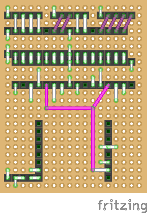
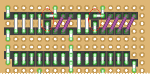
For convenience, I made a special version of the scheme, with only that upper wires:
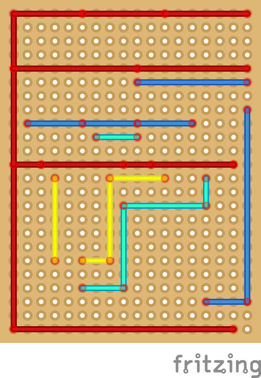
The scheme is crisp. In practice, it becomes rough, crooked, and imperfect:
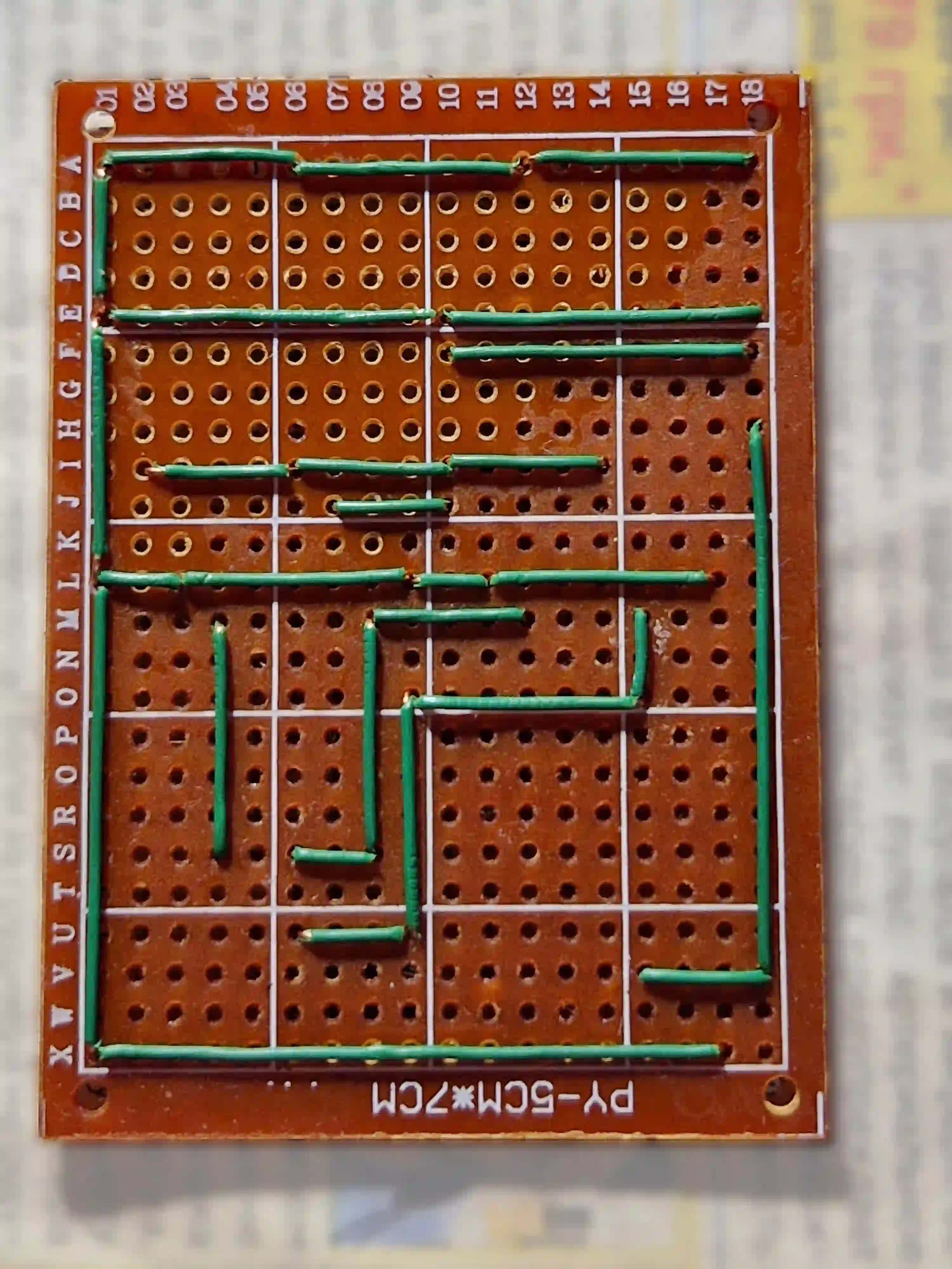
For the future: it turned out that the scheme is not so good. If you look closely, there are two places on the board (L01 and E01) where three wires should fit into one hole. Two such wires (cores from ethernet cable) fits well, and three do not fit. I had to drill those holes wider. (I know how to slightly change the scheme in the next version and avoid such “triple” joints with minimal effort).
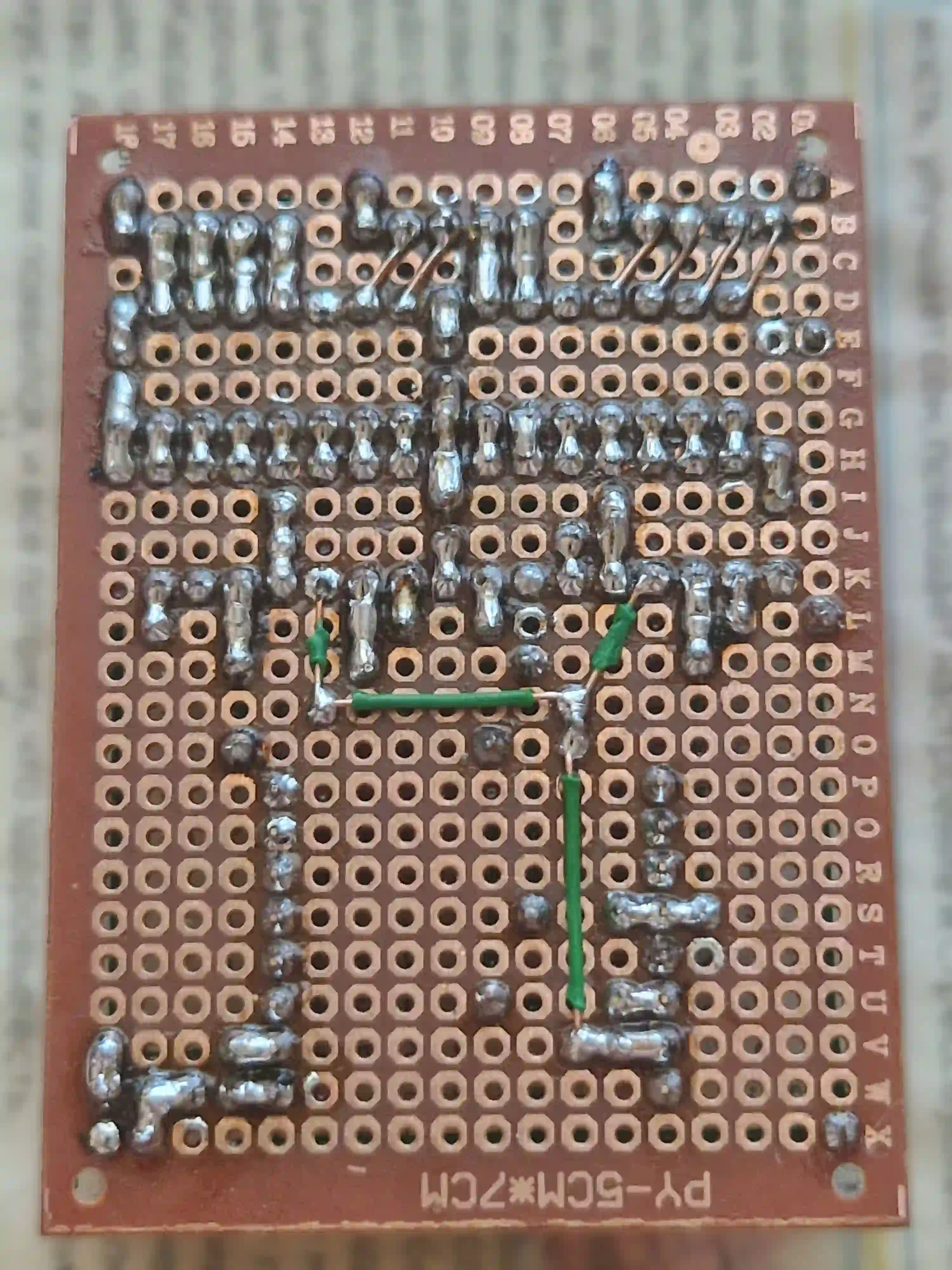
Okay. Let’s go. Next, I simply solder these wires to the matching pads. In the next photo, the soldering points are not visible (they are on the other side), but you can guess about the soldering, and not only by the rosin spots:
Obviously, it is better to use the proper mounting wire with heat-resistant insulation :)
While I was soldering, I constantly checked myself, tested the circuit. The very first board screwed up at this stage: it turned out that the getinax piece was defective. (I decided not to post the photo, well, to hell with it). Okay, I merely took another perfboard. Pros and cons of using the cheapest crap.
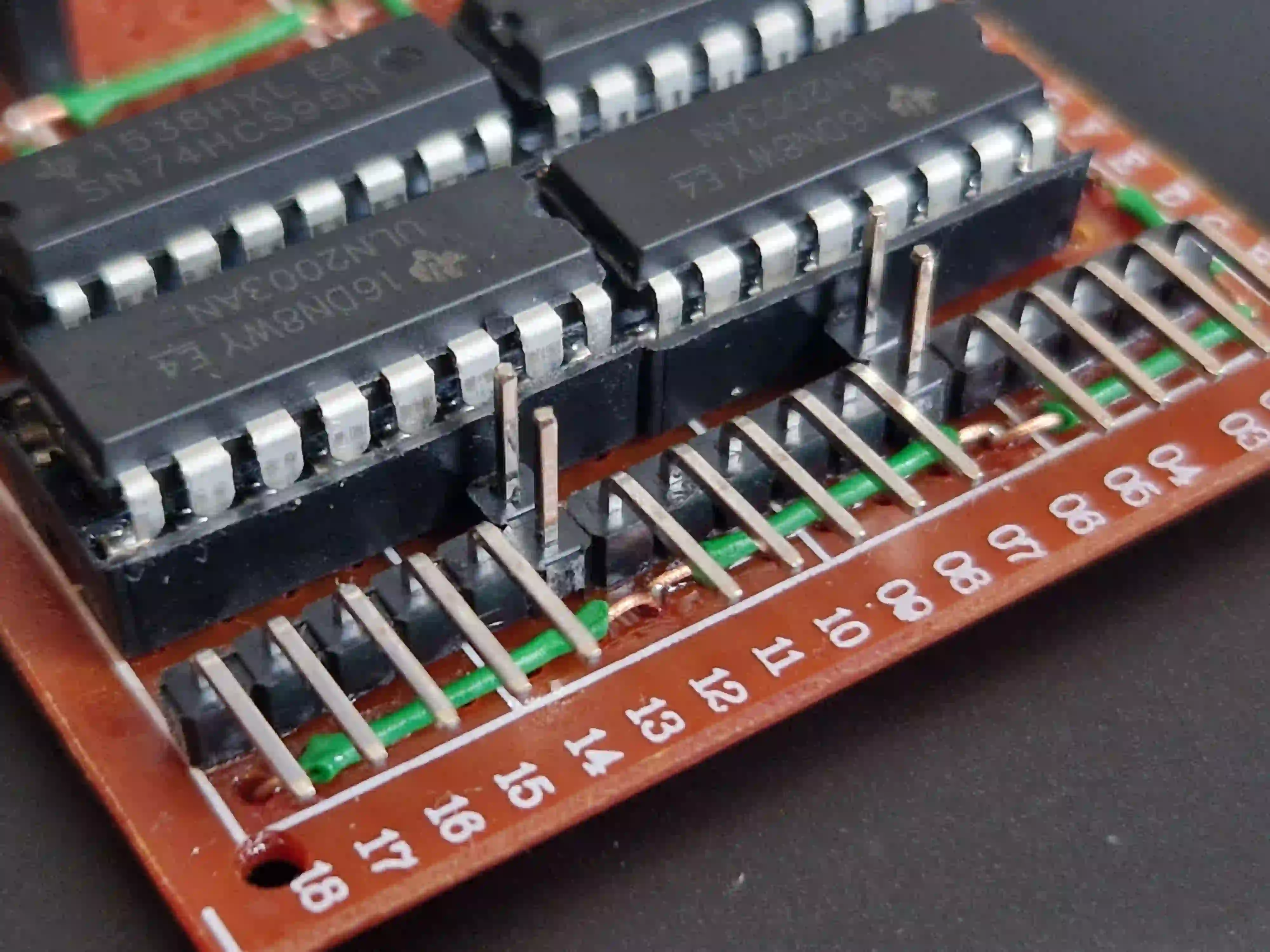
At the next stage, I have to place sockets for chips in DIP-16 cases and various contacts for everything else. The most troublesome are the contacts for the motors: I couldn’t find the right keyed XH connector (it should have been something like XH2.54-5P), so I use whatever I can find, a regular 5-pin headers. Operation will require attention and care to not accidentally connect the motor on the wrong side.
This is how the board looks like with all contacts installed:
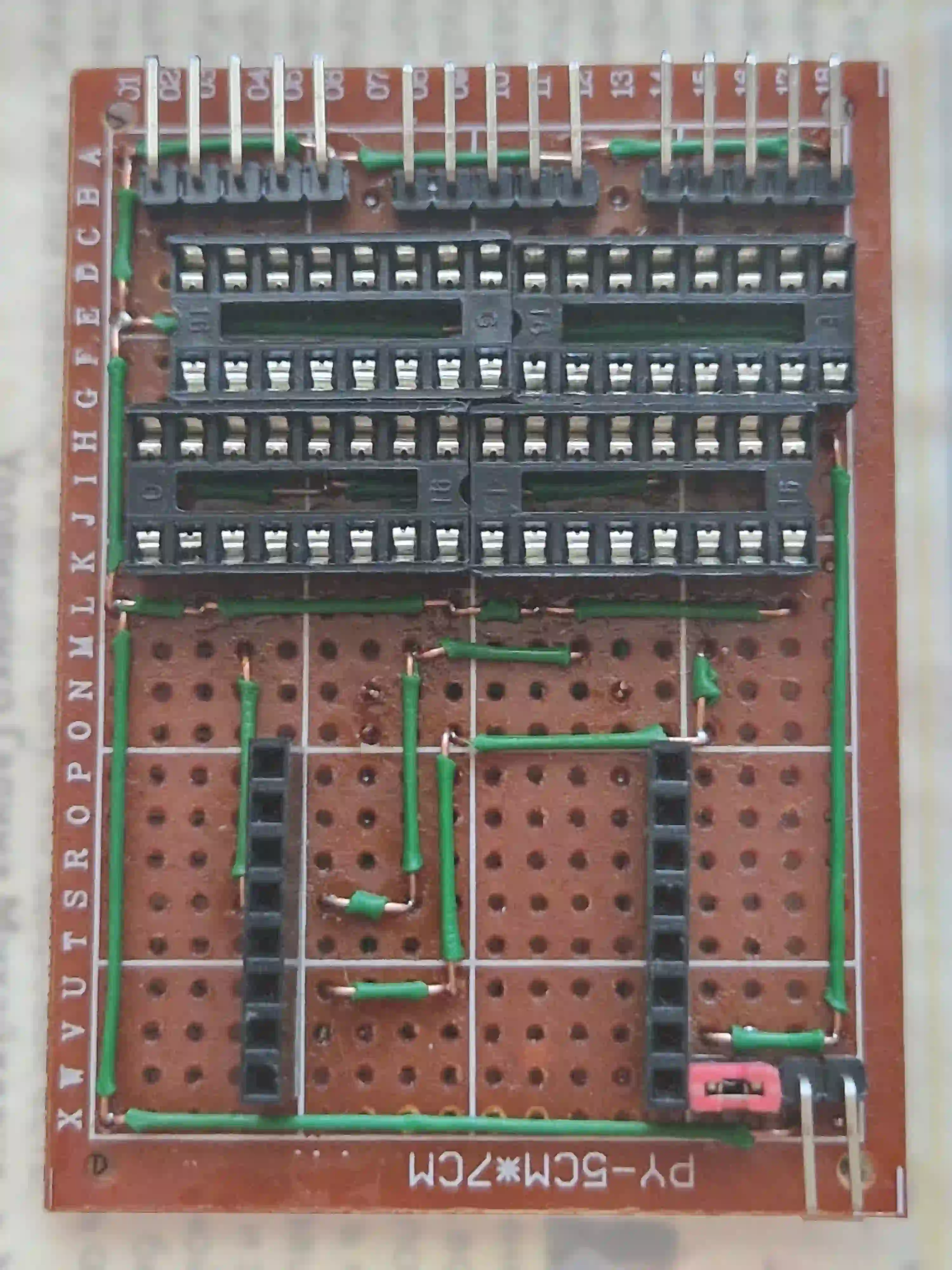
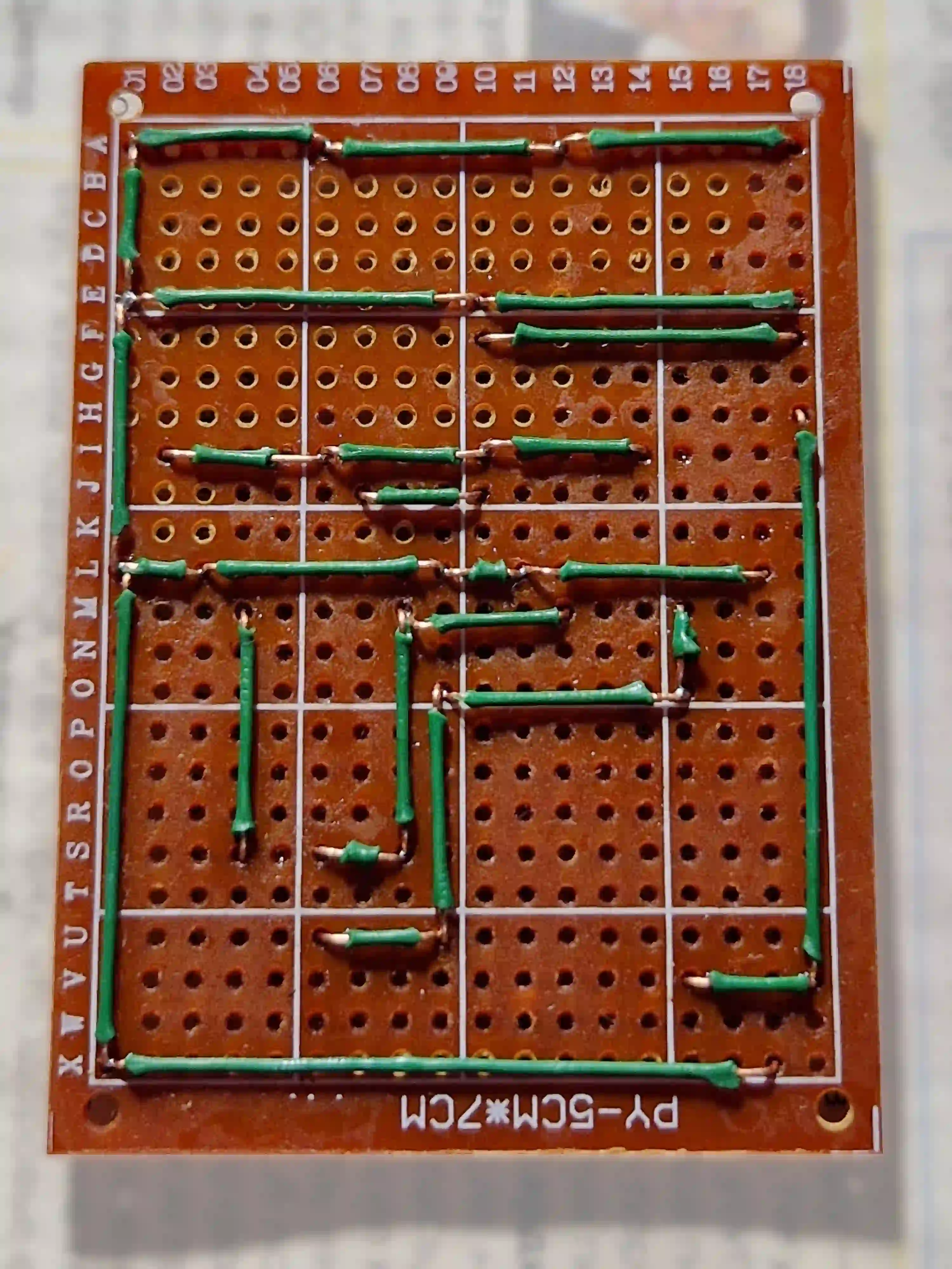
For the convenience of this stage, I created another auxiliary scheme: what, actually, will need to be soldered. Relative to the main circuit, it is horizontally mirrored (how I actually see the back of the board).
Colored connections is a wire, white is solder drops:
After all, it comes like this:
Yes, not so good. I see that points E01 and B04 are poorly soldered. I also see other problems: solder got into some places that are not in use (especially E02, L08, X18). But while soldering, I tested connections carefully and asserted that it matched the scheme.
Well, I’m just learning how to solder.
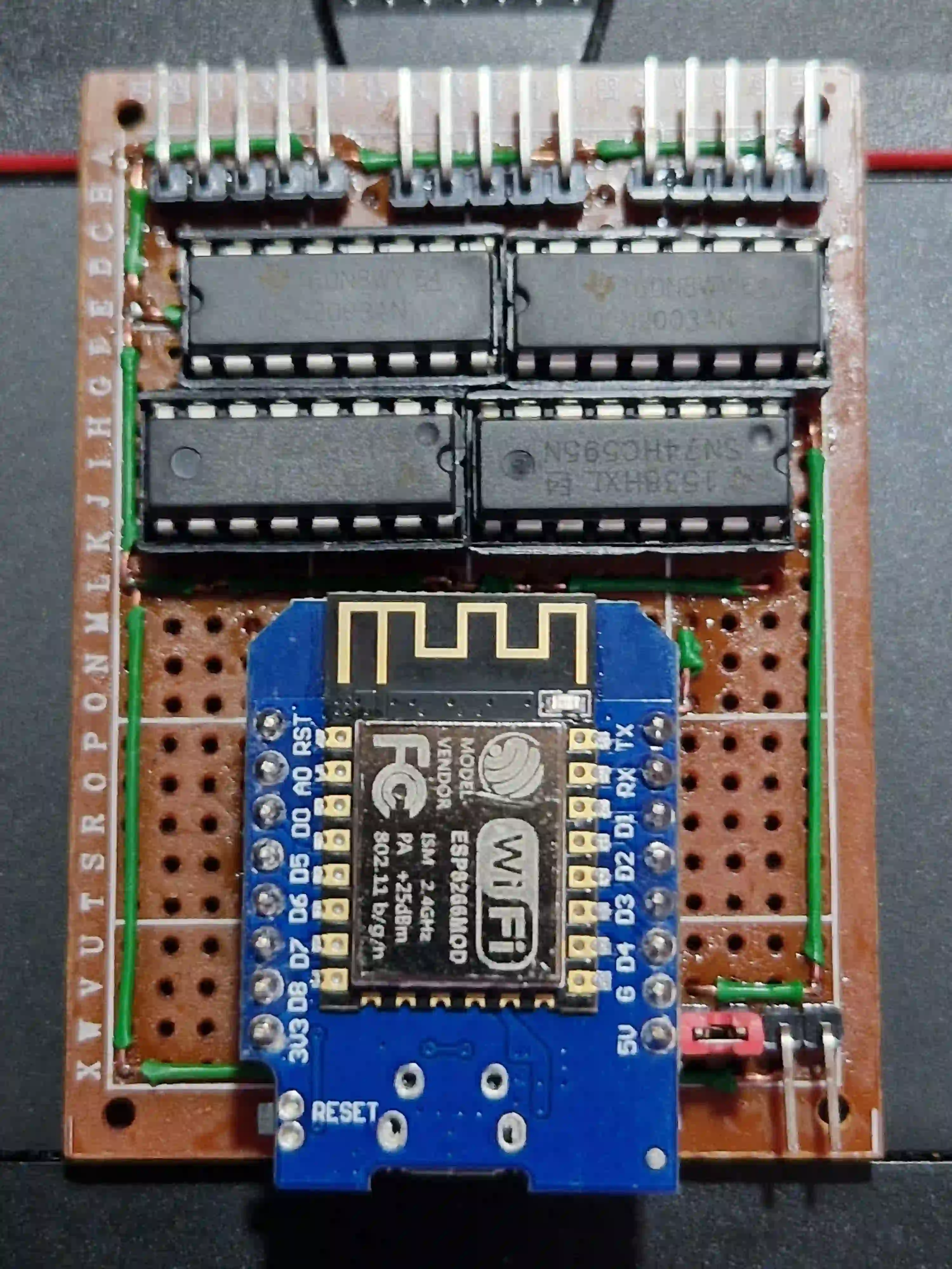
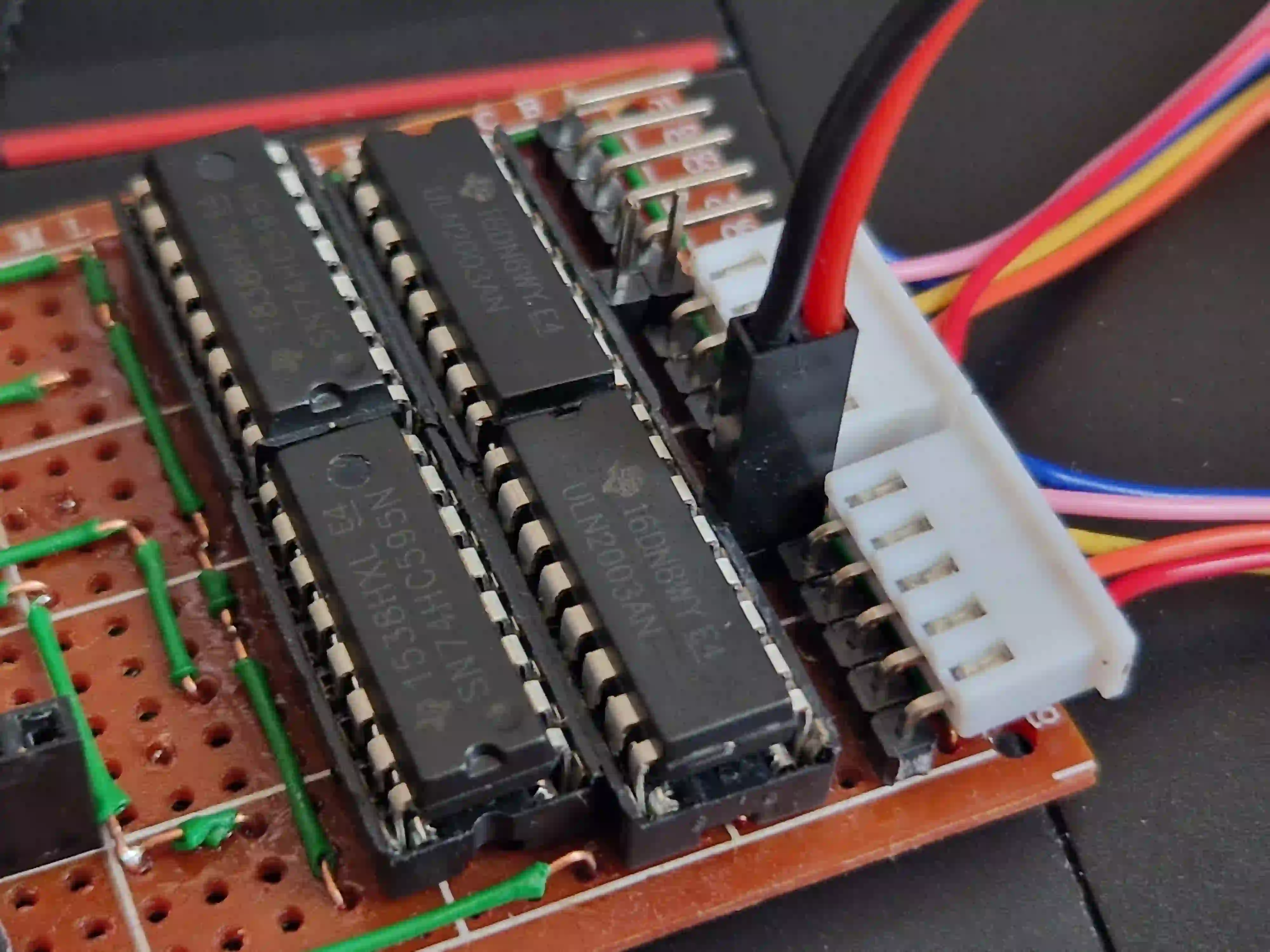
That’s how the assembled board with installed chips and with the WeMos D1 mini module looks like.
Software
Two connected 8-bit shift registers have 16 outputs. Bits 0 and 8 are difficult to use, because they are placed in the middle of a dense mess of wires. So they should be sacrificed.
The other 14 pins go directly and straight to the ULN2003 inputs, each of which has exactly 7 inputs and 7 outputs. But only 12 of these 14 outputs are used, because that’s what we need to control three stepper motors. Two more outputs remain unused. For ease of installation, let it be bits 5 and 11.
Let’s assume we have three stepper motors: A, B and C. Each has 4 windings: A1–A4, B1–B4, C1–C4.
| bit | 15 | 14 | 13 | 12 | 11 | 10 | 9 | 8 | 7 | 6 | 5 | 4 | 3 | 2 | 1 | 0 |
|---|---|---|---|---|---|---|---|---|---|---|---|---|---|---|---|---|
| winding | C4 | C3 | C2 | C1 | — | B4 | B3 | — | B2 | B1 | — | A4 | A3 | A2 | A1 | — |
I haven’t made acceptable software yet, I just quickly made something simple and dirty on MicroPython: a module for managing shift registers, a module for controlling stepper motors and a simple demonstration of using these modules.
File myShiftRegister.py
At first I made a simple bit-bang version (the SPI can be emulated on any GPIO), and after that I started using the proper SPI hardware interface.
SPI can be really fast. The hardware SPI in the ESP8266 can run at speeds up to 80 MHz.
On the other hand, the SN74HC595 shift registers powered with 5 V can operate at a speed up to 25 MHz. I didn’t realize it until I started looking for error cause :) because at a speed three times higher than the allowed, they started to glitch a little.
import machine

# WeMos board: D7 (GPIO13), SPI MOSI
# 74HC595: DS (Serial data input)
dataPin = machine.Pin(13, machine.Pin.OUT)

# WeMos board: D5 (GPIO14), SPI SCLK
# 74HC595: SH_CP (Shift register clock pin)
clockPin = machine.Pin(14, machine.Pin.OUT)

# WeMos board: D8 (GPIO15), SPI CS
# 74HC595: ST_CP (Storage register clock pin)
latchPin = machine.Pin(15, machine.Pin.OUT)

# Can I use hardware SPI? Yes.
spi = machine.SPI(1, baudrate=20000000, polarity=0, phase=0)
# Beware: if I define the hardware SPI, I will be not able to use bitbang version

# Or I can use SoftSPI
# Dunno why I cannot just say miso=None there
#spi = machine.SoftSPI(baudrate=100000, polarity=0, phase=0, sck=clockPin, mosi=dataPin, miso=machine.Pin(12))

def write74HC595_spi(data, num_bits=8):
    spi.write(data.to_bytes(num_bits >> 3, 'big'))
    latchPin.value(1)
    latchPin.value(0)

# And that's mostly for debugging
def write74HC595_bitbang(data, num_bits=8):
    for i in range(num_bits-1, -1, -1):
        #print((data >> i) & 1, end='')
        dataPin.value((data >> i) & 1)
        clockPin.value(1)
        clockPin.value(0)
    latchPin.value(1)
    latchPin.value(0)
    #print('')

write74HC595 = write74HC595_spi
#write74HC595 = write74HC595_bitbang

# On start, set all that to zeroes
clockPin.value(0)
latchPin.value(0)
write74HC595(0, 16)
File myStepper.py
Everything is more or less usual there, everything is almost like we do it for Arduino, but only with nuance that the windings are controlled through the shift register.
I use the full-step sequence, the simplest and the best. When the engine is inactive, I turn off all its windings.
I noticed that my stepper motors from two different batches (maybe even different manufacturers) have different winding sequence. The same control sequence moves the engine shaft clockwise or counterclockwise, depending on which batch the engine is from. And it seems to be a widespread problem. This should be taken into account in the future.
from myShiftRegister import write74HC595

class MyStepper:
    outputBits = 0                  # part of 74HC595 output
    stepActual = 0
    stepTarget = 0
    _delta = 0

    def __init__(self, stepBitMask):
        assert len(stepBitMask) == 4
        self.stepBitMask = stepBitMask

    def target(self, target):
        self.stepTarget = target
        self._delta = 1 if self.stepActual < self.stepTarget else -1

    def update(self):
        if (self.stepActual == self.stepTarget):
            self.outputBits = 0     # turn the coils off after last step
            return

        if (self.outputBits):       # if the coils is already turned on
            self.stepActual += self._delta
        # else: turn on the coils at last position, wait one step cycle

        self.outputBits = self.stepBitMask[self.stepActual & 3]

# my 2x SN74HC595 + 2x ULN2003AN scheme, version 4c:
#
#  bit: 15 14 13 12 11 10  9  8  7  6  5  4  3  2  1  0
# coil: C4 C3 C2 C1 -- B4 B3 -- B2 B1 -- A4 A3 A2 A1 --

motor1 = MyStepper([ 0b1100 << 1, 0b0110 << 1, 0b0011 << 1, 0b1001 << 1 ])
motor2 = MyStepper([ 0b11000 << 6, 0b01010 << 6, 0b00011 << 6, 0b10001 << 6 ])
motor3 = MyStepper([ 0b1100 << 12, 0b0110 << 12, 0b0011 << 12, 0b1001 << 12 ])

def oneStep():
    motor1.update()
    motor2.update()
    motor3.update()
    bitmask = motor1.outputBits | motor2.outputBits | motor3.outputBits
    write74HC595(bitmask, 16)
File main.py
I couldn’t think of anything better than just rotate all three motors. For now, I use no more than two motors at a time, just as a precaution. With proper power supply, you can use all three at once.
import myStepper, time

myStepper.motor1.target(1024)
for x in range(770):
    myStepper.oneStep()
    time.sleep_ms(3)

myStepper.motor2.target(1024)
for x in range(770):
    myStepper.oneStep()
    time.sleep_ms(3)

myStepper.motor3.target(1024)
for x in range(1026):
    myStepper.oneStep()
    time.sleep_ms(3)
It’s rotating! :)
A short YouTube demonstration video: https://youtu.be/qPV8w360FCU
Next I shall do this properly. That’s ESP8266, it has Wi-Fi on board. According to my plan, the next version of the firmware will communicate with the outer world via MQTT.
Possible modifications
Of course, the scheme can be improved. Here I note a few simple possible ways for expanding an already existing scheme.
How to use two more outputs of ULN2003
It seems not no difficult to use bits 5 and 11 for something else. It’s somehow tight, but seems possible.
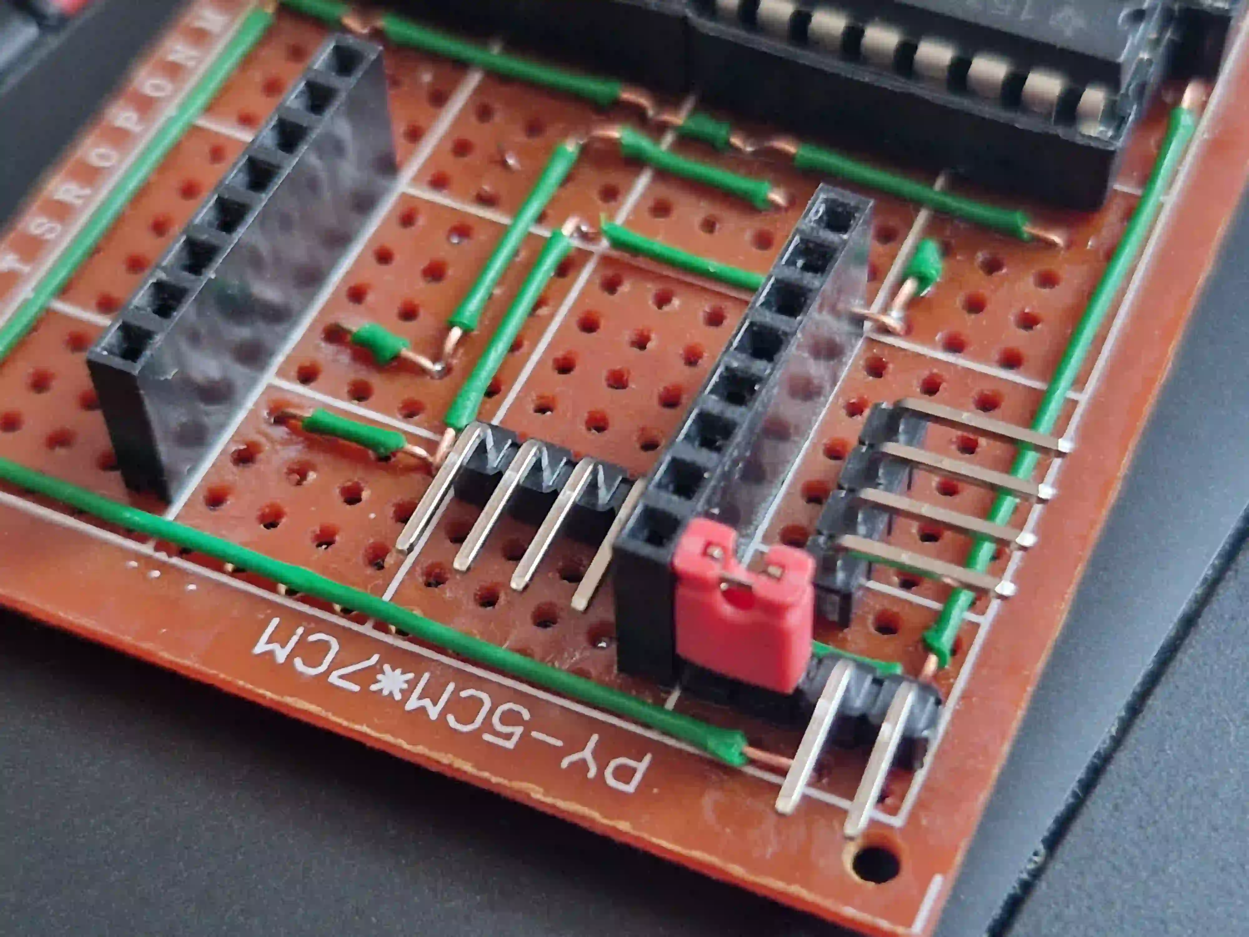
On the photo, the contacts are not actually soldered, it is just a “try-on” to evaluate the placement:
Standard DuPont connectors and stepper motor contacts seem to fit there:
Why not? You can connect an LED, or an active speaker (buzzer), or something else. Solenoid. Laser. Two lasers :)
How to connect something to the ESP8266 itself
I²C bus, limit switch, PWM for the servo? There is space, there are free GPIOs, something can be added.
Of course, this “something” should be connected simply, without fuss. That is, if there will be I²C, it should be a convenient 4-pin connector, for example: VCC (probably 3.3 V), GND, SCL, SDA.
If you connect a servo drive, then, accordingly, it should have a standard three-pin connector (GND, +5V, PWM). Just have to decide how to solder it.
Here is also only a “try-on”, even without a scheme, just to estimate free space on the board:
In addition, I want to say a couple of words about limit switches. They are often used when a printer, plotter or CNC machine is turned on, so the firmware can find the origin of the coordinates (because it is not known at which physical state the machine was at the time of MCU start).
How many limit switches are needed for three motors controlling three independent axes? I think that for convenience there can be any number of them, for example, one switch for each axis; but they must be connected in parallel to one GPIO. The axis positioning should be done sequentially.
The algorithm is simple: we move one axis until the limit switch is triggered, then go back a little until it is released, repeat the actions for the next axis. That’s all! :) The machine is at the starting position.
Conclusions
This is my first “permanent” board.
Yes, this is an extremely simple scheme. But I came up with that idea, tested it on a solderless mock-up, drew a realistic scheme, soldered it, wrote the firmware, sorted out the glitches. It turned out that it really works and really does exactly what it was intended to do.
I am quite satisfied. I like my hobby.